Twinning the campus.
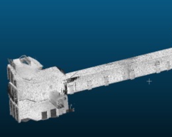
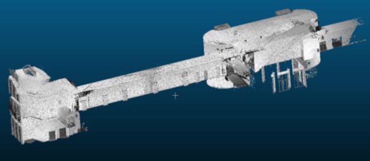
A georeferenced digital twin of a multi-floor structure — built by fusing static terrestrial and mobile backpack laser scanning into one centimetre-accurate point cloud, as part of the TUM2Twin initiative to make the Munich campus the most surveyed location on Earth.
Two scanners, one coordinate system
Digital twins are moving from novelty to infrastructure — feeding real-time monitoring of buildings, facility management and urban planning. But capturing a multi-floor interior accurately enough to trust is hard. Terrestrial laser scanning (TLS) delivers millimetre precision yet is static and line-of-sight, demanding many tripod positions and careful control. Mobile laser scanning (MLS) sweeps through corridors and stairwells in minutes, but trades accuracy for speed and accumulates drift where features are sparse.
Neither method alone produces a complete, reliable twin of a complex building. The real problem is integration: reconciling two datasets of different density, noise and perspective into a single, floor-accurate, georeferenced model.
The question was never which scanner is better — it was how precisely the fast one and the accurate one agree once they share a datum.
A controlled, target-based workflow
GWO followed the conventional geodetic survey sequence — establish control, place targets, then capture — across the ground and first floors, each divided into four working sections. A total-station control network of points such as TS_N_03, TS_M_02 and TS_S_00, interconnected by measured baselines, formed the spatial backbone for georeferencing every scan.
Targets were positioned so at least three were visible from any single scan station, distributed across walls and ceilings to constrain the registration geometry and suppress error from poorly-shaped target triangles.
- Leica RTC360 TLS
- High-speed terrestrial scanning of interior corridor sections.
- Leica ScanStation P50 TLS
- Long-range, high-precision static capture.
- Z+F FlexScan MLS
- Backpack-mounted SLAM scanning for continuous multi-floor coverage.
- Leica Cyclone Registration
- Target-based TLS registration & point-cloud cleaning.
- CloudCompare Analysis
- ICP fine registration and M3C2 distance comparison.
From raw scans to a unified twin
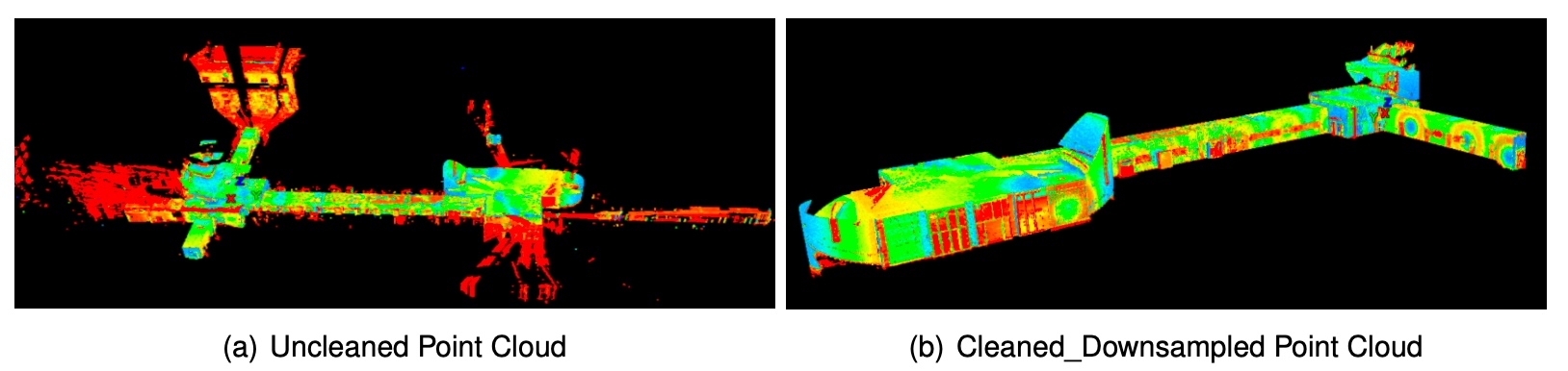
Target-based registration in Leica Cyclone aligned the individual TLS scans with high accuracy. The merged cloud was then cleaned — removing moving people, occlusions and stray returns through windows — and down-sampled with the Unify Clouds tool to a defined minimum point spacing, cutting file size and compute load while preserving structure. Finally, the control-point list from the geodetic network georeferenced the whole dataset into a real-world coordinate frame.
How closely do they agree?
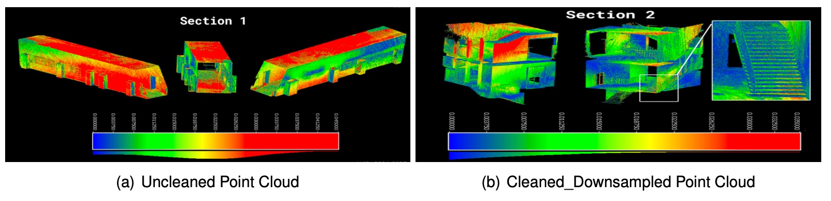
With the TLS cloud as reference, the MLS cloud was roughly aligned by hand, then refined with the Iterative Closest Point (ICP) algorithm. Because the full dataset was too large to process at once, the comparison ran on smaller segmented sections. The Multiscale Model-to-Model Cloud Comparison (M3C2) plugin then measured point-to-point distances between the two clouds — green for close agreement, red where the MLS sits further from the reference, blue where it sits nearer.
What the comparison proved
Across the tested sections the two clouds were predominantly in agreement — most M3C2 surfaces returned green, confirming that mobile scanning reaches a quality acceptable for digital-twin work. Deviations stayed within 10–20 mm on planar surfaces and widened to 10–20 cm only in geometrically complex, feature-sparse areas, consistent with the known tendency of MLS to drift where the SLAM solution has little to lock onto.
The practical conclusion is a complementary one: pair TLS for high precision with MLS for fast, comprehensive coverage, and surveyors gain efficiency without sacrificing the accuracy a trustworthy twin demands.
Where it goes next
- 01
Enhanced SLAM for MLS
Reduce drift in feature-sparse corridors and stairwells through improved mobile-scanning algorithms.
- 02
Standardised uncertainty quantification
Consistent procedures for stating point-cloud accuracy, so twins carry defensible error budgets.
- 03
Deeper BIM integration
Bind the as-built geometry to Building Information Models for full lifecycle facility management.
- 04
Scale beyond two floors
Extend the workflow to whole multi-storey buildings and, ultimately, the full campus twin.
The project lays an end-to-end foundation — from sensor placement to validated output — that turns a one-off scan into a repeatable method for georeferenced digital twins.
Sources & data
This case study is a condensed summary of independent research. For full data sources, datasets and references, please get in touch.
Need a reality capture you can build on?
If you need an as-built model with a defensible accuracy budget — for a building, a site or a campus — tell us about the structure and what the twin has to support.